What this model teaches
Apply a 10 V step to an original series resistor–inductor–capacitor teaching circuit and compare current and charge with its damped closed-form response.
Two integrators implement dq/dt = i and di/dt = (10 − 8i − q/0.002)/0.4. The analytical damping is 10 s⁻¹ and damped angular frequency is √1150 rad/s. The charge approaches C·E = 0.02 C.
Original series-circuit topology with zero stored energy at initialization. Equation ports use explicit SI numerical mapping (1 unit = 1 A, 1 C or 1 V) because this preserved equation runtime has no charge-rate port type. The inputs are authored synthetic teaching choices. No measured cell, material dataset or external software trace is reproduced. Passing verifies these numerical implementations against analytical equations; it does not establish hardware accuracy, safety or parity with another product. Maximum-error gates are fixed before execution. RMSE weights accepted solver samples equally; it is not a uniform-time integral. Ideal linear components and a prescribed ideal voltage step. Parasitics, switching losses and physical component tolerances are omitted. This is an equation graph, not a conserving-network topology test.
Open and run
Open prepared examples and select Series RLC: step response from rest. Choose Run prepared model for a fresh native solve. The public viewer is read-only; the displayed Pro editor is a separate product and may require a separately saved model. Download the complete model and retained run to inspect the exact graph and outputs.
This original graph has 7 blocks, 8 connections and 3 compared signals. It carries reference version 2.
Prescribed inputs
| Input | Value | Unit |
|---|---|---|
| Series resistance | 8 | Ω |
| Inductance | 0.4 | H |
| Capacitance | 0.002 | F |
| Applied voltage | 10 | V |
| Initial current | 0 | A |
| Initial charge | 0 | C |
Blocks and parameters
| Block ID | Type | Parameters |
|---|---|---|
capacitive-rate | gain | gain=-1250; inputQuantity=dimensionless |
charge | integrator | gain=1; initial=0; rateQuantity=dimensionless |
current | integrator | gain=1; initial=0; rateQuantity=dimensionless |
current-rate | sum | inputs=3 |
input-voltage | constant | value=10 |
resistive-rate | gain | gain=-20; inputQuantity=dimensionless |
source-rate | gain | gain=2.5; inputQuantity=dimensionless |
The runtime connections in the downloaded model are authoritative. A gain changes the mathematical coefficient only when it is wired to the stated signal.
Original numerical plot
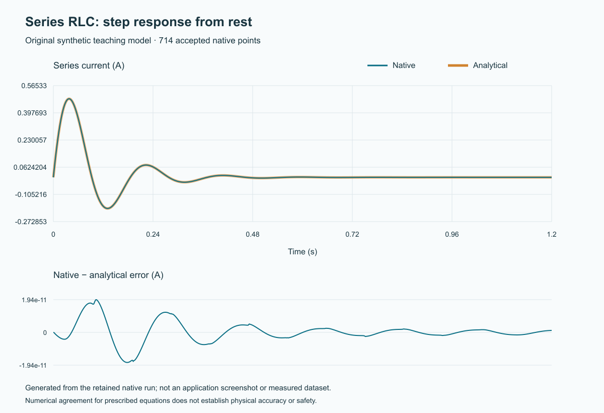
This is an original plot generated from the retained native trace, not a screenshot and not a downloaded external waveform. The overlaid reference is evaluated independently at each accepted solver time.
Recorded numerical checks
A fresh run on 2026-10-28T17:13:51.851Z retained 714 output points. The execution report includes every native point, analytical comparison and source fingerprint.
| Signal | Maximum absolute error | Fixed gate | Points |
|---|---|---|---|
| Series current | 1.936704963068081e-11 | 1e-7 | 714 |
| Capacitor charge | 5.983789852503918e-13 | 1e-7 | 714 |
| Applied voltage | 0 | 1e-7 | 714 |
Errors and gates use each signal's stated unit. The check requires the complete 0–1.2 s interval, every accepted output point, finite values, correct block quantities, current reference binding and exact solver settings. It rejects missing current-switch instants for the pulse model.
Try an edit carefully
Changing a prescribed input creates a different mathematical experiment. The original comparison should then fail; do not enlarge its gate to accept changed equations. Create a separately justified contract and oracle for a new experiment.
Equations and provenance
Read the original input contract, how to interpret comparisons and model workflow. These numbers are hypothetical choices. Passing establishes numerical agreement for these equations only. No measured accuracy, safety or external-software parity is claimed.