🛠️ Simulation Objective & Use Case
Size a 51.2 V-class LFP battery for four hours at 2 kW DC. Start with the load, then inspect a 16S1P assembly of EVE LF280K cells in Lemonergy. This example helps with early storage sizing and interpreting a simulated state-of-charge trace.
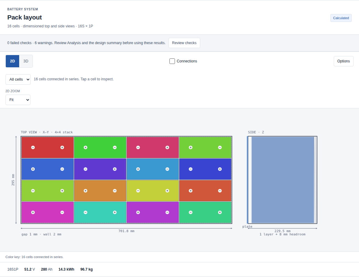
| Quick sizing check | Value | Meaning |
|---|---|---|
| Configuration | 16S1P | Sixteen 280 Ah cells in series |
| Nominal pack voltage | 51.2 V | 16 × 3.2 V |
| Nominal capacity | 280 Ah | Series connection does not add Ah |
| Calculated nominal energy | 14.336 kWh | 51.2 V × 280 Ah |
| Declared DC duty | 2 kW for 4 h | 8 kWh requested at the battery output |
| Nominal energy at 80% depth of discharge | 11.4688 kWh | Initial sizing allowance before losses and other derating |
| Nominal cell mass | 86.72 kg | Cells only; enclosure and other hardware are additional |
The nominal allowance exceeds the requested 8 kWh. Next, check whether the simulated pack serves the duty while retaining reserve. These are battery-side DC inputs: include inverter loss, auxiliaries and the actual load profile when adapting the example to a home.
Use the native case download above, then choose Open Pack Designer. The supplied file retains the declared duty as well as the cell and pack settings.
🧮 Mathematical Model & Equations
Vnom,pack = S × Vnom,cell
Qpack = P × Qcell
Enom = Vnom,pack × Qpack
Eduty = Pload × t
Eallowance = DoD × Enom
Inominal = Pload / Vnom,pack
Rpack = (S / P) × Rcell
S and P are series and parallel counts; voltage is in V and capacity in Ah. Energy is in Wh when power Pload is in W and time t is in hours. DoD is the selected usable fraction for this initial budget. Inominal is a sizing estimate in A, not the simulated current at every time point.
For this case, Eduty = 2,000 × 4 = 8,000 Wh and Eallowance = 0.8 × 14,336 = 11,468.8 Wh. Dividing that allowance by 2 kW gives 5.7344 hours before electrical losses, voltage limits, temperature effects or ageing allowances; it is not a guaranteed backup duration.
The application's mission model uses a state-of-charge-dependent open-circuit voltage, a resistive voltage drop and coulomb counting:
Rmission = Rpack + Rinterconnect
Vterminal = VOCV(SoC) − I × Rmission
Pload = Vterminal × I
ΔSoC = −I × Δt / (3,600 × Qpack)
Here Rmission includes the cell network and the model’s interconnect allowance; Δt is in seconds and SoC is a fraction. Consequently, the final simulated SoC need not equal a simple subtraction of 8 kWh from nominal energy. The built-in OCV shape is a chemistry-class approximation, not an LF280K-specific measured OCV map.
The independent static Rust checker and reproduction commands are included under verification/pack-design/ in the corresponding source bundle linked in the page footer.
📊 Model Parameters & Reference Data
| Parameter | Symbol | Baseline value | Unit | Source and conditions |
|---|---|---|---|---|
| Cell nominal capacity | Qcell | 280 | Ah | EVE sheet: 0.5C, 25 ± 2 °C, 2.5–3.65 V |
| Cell nominal voltage | Vnom,cell | 3.2 | V | Same manufacturer rating conditions |
| Cell voltage bounds | Vmin / Vmax | 2.5 / 3.65 | V | Manufacturer cut-off entries; not a recommended everyday operating window |
| Cell nominal mass | mcell | 5.420 | kg | Manufacturer value with ±0.300 kg tolerance |
| Cell DC resistance used by the model | Rcell | 0.00038 | Ω | Catalogue/scenario estimate; not a verified LF280K DC measurement |
| Charging temperature window | Tcharge | 0 to 55 | °C | Manufacturer operating range |
| Discharging temperature window | Tdischarge | −20 to 55 | °C | Manufacturer operating range |
| Declared battery-side load | Pload | 2,000 | W | Authored constant duty, not measured household consumption |
| Duty duration | t | 4 | h | Authored scenario |
| Selected depth of discharge | DoD | 0.80 | fraction | Sizing assumption; review reserve for the application |
| Starting state of charge | SoC0 | 1.00 | fraction | Captured native mission input |
| Mission ambient temperature | Tamb | 35 | °C | Captured design-window input |
| Retained load samples | count × interval | 240 × 60 | s | Constant 2 kW synthetic upload retained in the native case |
| Total mission resistance | Rmission | 0.02608 | Ω | 6.08 mΩ cell network plus the model's 20 mΩ interconnect allowance |
| Calculated enclosure envelope | x × y × z | 701.8 × 295 × 229.5 | mm | Native result with stacked upright cells, 4 cells per row and one layer |
The LF280K source record links the exact manufacturer sheet. Its ≤0.25 mΩ impedance specification is an AC measurement at 1 kHz and 30–40% SoC. It does not establish the DC resistance needed for this simulation; multiplying that AC value by a convenient factor is not a measurement. Treat heat and voltage-loss estimates as sensitive to the assumed 0.38 mΩ.
The sheet's prismatic dimensions also depend on stated SoC and fixture-compression conditions. A cell outline alone does not establish enclosure clearance, swelling allowance, structural compression or a finished pack envelope.
For reproducibility, the independent Rust arithmetic check covers static series/parallel identities with a relative tolerance of 1e−9 and a unit-scale absolute floor. This verifies implementation agreement, not accuracy of the estimated physical parameters. The model does not predict ageing or product lifetime.
The captured layout uses 1 mm cell spacing, 2 mm walls, 8 mm headroom and a 10 mm underside allowance. Selected components include an aluminium busbar, aerogel barrier, bottom cold plate, gap filler and extruded aluminium enclosure. Their model allowances explain the envelope; they are not a detailed mechanical drawing. The case also retains the preset regulatory evaluation date 18 February 2027, an assessment assumption distinct from this article's publication date. Its screening messages do not establish compliance.
🚀 Step-by-Step Lemonergy Implementation
- Download the storage case and open Pack Designer. Choose Engineering workbench if the simple sizing view is active.
- In Cases → Import case file, select the JSON file. Wait for the verified-open message; confirm EVE LF280K, 16S1P, 51.2 V and 14.336 kWh.
- Inspect the retained four-hour duty: 2 kW, 100% starting SoC and 35 °C ambient. Use Design for the arrangement and Sim for the mission output; click Mission traces to enlarge the chart.
- Read final SoC, unmet demand and the current, voltage, temperature and packaging findings together.
- Choose Save case to keep this version locally and Export case file for a portable model. Export results JSON saves a calculated report.
For a first edit, choose Duplicate case and increase backup duration while keeping DC power and cell choice fixed. Update the duty as well as the energy requirement, then compare against the saved baseline; changing a target alone does not create a longer simulated trace.
If import fails, preserve the current case and read the error. Check that you selected a native case rather than a results report. A result-identity mismatch requires compatible engine/catalogue inputs; do not overwrite its checksum.
📈 Expected Simulation Results
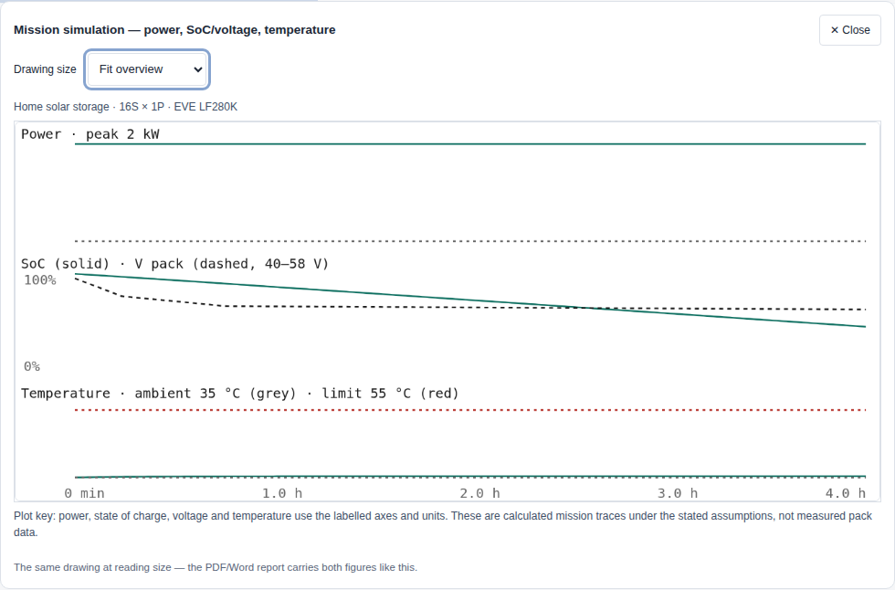
The verified native case serves the full four-hour duty with these calculated results:
| Mission result | Recorded value |
|---|---|
| Delivered DC energy | 8.000 kWh |
| Final state of charge | 45.39% |
| Unmet energy demand | 0 Wh |
| Minimum terminal voltage | 51.616 V |
| Maximum lumped temperature | 35.403 °C |
| Modelled electrical loss | 152.490 Wh |
| Remaining design findings | 0 failed checks; 6 warnings |
The static result should show 16 cells, 280 Ah, 51.2 V and 14,336 Wh calculated nominal energy. Check equipment against the complete 40–58.4 V range implied by the stated cell limits.
At nominal voltage, 2 kW corresponds to approximately 39.063 A; the assumed cell network is 6.08 mΩ. These are sizing checkpoints. The current trace varies with the model's terminal voltage.
During discharge, SoC falls as charge is drawn. Read the end-of-duty point and unmet-energy output to decide whether the complete declared load is served.
Model limits: six warnings remain, covering enclosure breathing/pressure relief, short-circuit screens and unresolved regulatory classification. Estimated DC resistance, a generic OCV shape and lumped temperature do not establish local hot spots or finished-system performance. This is a sizing study, not a qualified battery product or residential installation design.
📚 References & Provenance
Source: EVE LF280K manufacturer sheet, page 1, specification table and drawing; accessed 11 October 2026. Revision and publication date are unverified. The expandable parameter table separates its ratings from the assumed 0.38 mΩ DC resistance and synthetic load.
Verification ID: lfp-storage-14kwh. The native case retains inputs, duty, authoring settings and result binding; its download provenance supplies the checksum. Pack calculation uses the existing browser engine; independent static arithmetic checks use Rust.
Fresh-session import preserved the complete native snapshot and binding, and the browser's numerical result matched replay. The corresponding source bundle retains this case's verification record; browser and Node engine-selection explanations are recorded separately.